| |
Displaying Results
NOTE: We assume that all analyses are done in radiologic conventions (right is left).
Setting this convention is described at beginning of Analysis Details.
Additional methods for display are described below.
- The Glass Brain - Default SPM Result Diplay
- Display your results on multiple slices of a template MRI
- Overlaying SPM results on a patientís own MRI
- Make 3D rendering of Results
The Glass Brain
In the Analysis section, we have already described how to display
results on the glass brain view.
The glass brain is the standard SPM results display.
Display your results on multiple slices of a template MRI
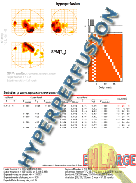
- Perform ISAS and reach the glass brain view of the results.
- You can now save just one, or both, of the hyper- and hypoperfusion "blobs" (regions of significant changes).
We will start by saving the hyperperfusion blobs.
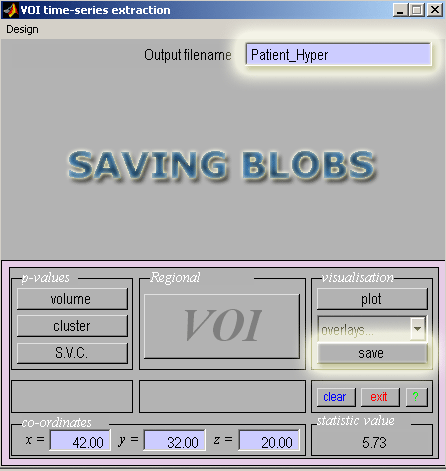
- Starting with the glass brain view of the hyperperfusion results click the Save button in the SPM interactive window.
- Enter a filename to save these blobs (ie. Patient_Hyper) as an image in the current directory.
- Next you may want to also save the hypoperfusion blobs so that you can overlay both sets of results on the MRI.
If so, then repeat the last two steps with the hypoperfusion results.
- After you have prepared your blobs, you are now ready to overlay your results on a template MRI
- Type display_slices at the Matlab prompt.
NOTE: In order to use the display_slices feature you must first have downloaded and installed the display_slices.m script.
- First select (without clicking Done) the MRI template ( you can use the single_subject_t1 image in the ..\smp2\canonical directory).
- Then select the blob images (hyper and/or hypo perfusion contrasts).
- Click Done.
- Next SPM will ask you what type of image you selected as your first image, click Structural
- Then a prompt will ask you the type of the second image you selected, click Blobs
- When asked what colormap to use enter red if the current set of blobs is from the hyperperfusion results (enter green for hypoperfusion); alternatively, you can use hot and winter)
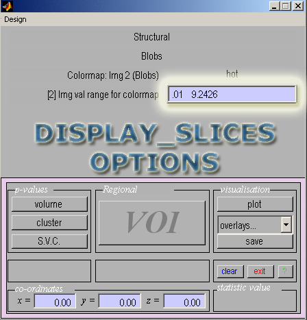
- Image value range: Enter .01 for the minimum value (replacing 0) to avoid a completely dark image. Leave the max value at the default.
- Now that you've added one set of blobs you may choose to add the other.
If so, repeat the step above and be sure to set the color map to a contrasting color from the previously selected one.
- Having finished selecting the images (structural and blobs) you will now enter the orientation that you would like the results to be displayed in (e.g. coronal)
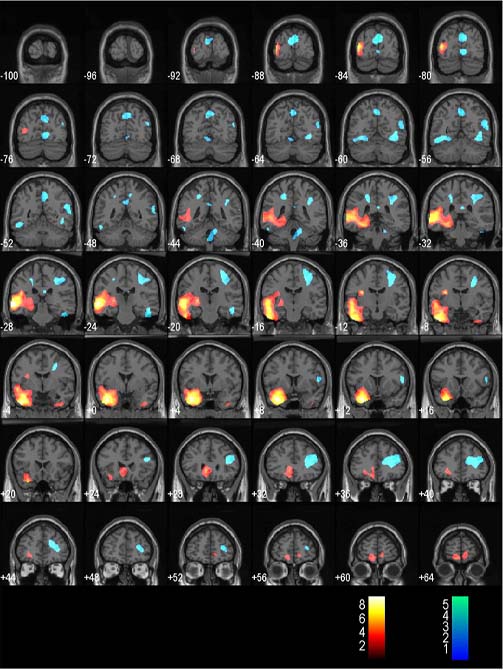
- Next you will be asked for the number of slices you want to display. The notation is X:Y:Z, where X is the first slice shown, Y is the distance between slices, and Z is the last slice shown.
For a coronal orientation -100:4:66 works well.
- Now you should see an image similar to the one below.
Overlaying SPM results on a patientís own MRI
- Perform an ISAS analysis so that you reach the glass brain view of the results.
- Save the "blobs" (regions of significant changes) from your hyper and hypoperfusion contrasts. You can save just one, or both, of the hyper- and hypoperfusion blobs.
We will start by saving the hyperperfusion blobs.
- Starting with the glass brain view of the hyperperfusion results click the Save button in the SPM interactive window.
- Enter a filename to save these blobs (ie. Patient_Hyper) as an image in the current directory.
- Next you may want to also save the hypoperfusion blobs so that you can overlay both sets of results on the MRI.
If so, then repeat the last two steps with the hypoperfusion results.

- Coregister
After you have prepared your blobs, you wil have to unwarp the SPM blobs back to the patient's own MRI space as follows:
- Obtain the patient's MRI and set the crosshairs just like it was done for the SPECT scans.
- Click Coregister from the SPM menu window to send the MRI and the realigned SPECT scans (interictal and ictal) into the same space.
- Number of Subjects: 1
- Which Option: Coregister and Reslice
- Target: patient's MRI image
- Object: meanSPECT image (meanFILENAME.img)
- Other images to be coregistered: Do not select any images
- If successful this step will produce, in your current directory, a SPECT image coregistered to the MRI (image is prefixed with an "r").
NOTE: You should make sure that the MRI and SPECT images are properly aligned by performing a CheckReg.
- Once the coregistration is complete, we will now spatially normalize the rmeanSPECT image to the same dimensions as the standard SPM2 SPECT template.
- Normalize
- Click on Normalize in the main SPM window
- Option: determine parameters and write normalized
- Select the template image: select the SPM2 SPECT template.
- Select the source image for subject 1: This should be the rmeanSPECT image you just created during the coregistration step.
- Select the images to write for subject 1: Select the same rmeanSPECT image file again (this is mainly just to check your work and see if SPM properly spatially normalized the files.)
- Deformation
Once you have spatially normalized your coregistered mean SPECT image, you can now apply an inverse
of the spatial normalization transformation matrix on your blobs. The normalized meanSPECT image will
be transferred to the original stereotactic space of the MRI by reversing the normalization. The hyperperfusion
and hypoperfusion blobs are transferred from SPM spect template space to the patient's own MRI space by means
of the same deformation.
This is achieved by employing the deformation toolbox.
- In the SPM Display window, click on Toolbox->Deformations. A deformations file menu will appear in the SPM results window.
- Click on Deformations->Deformations from sn.mat and load the normalization .mat file (rmean*sn.mat) found in your patient's analysis folder to create a deformation file (y*.img)
- Once a deformation file has been created, you must invert that deformation in order to unwarp your normalized SPM results.
Select Deformations->Invert Deformations and select your deformation (y*.img) file.
- Select your newly coregistered mean SPECT file (rmean*.img) as the basis for your inverses. Two new files will be created (1) a new inverse file iy*.img and (2) an associated .mat file.
- Go to Deformations->Apply Deformations. Depending on the number of files you want
to unwarp that is the number of subjects you will select (If we have 2 perfusion contrasts, hyper and
hypo, then we will select number of subjects=2).
- In the SPMget window entitled "Select deformation field 1", select the inverted
deformation (iy*.img) file as the template and click done.
- In the SPMget window entitled "Image(s) to warp (1)", select your hyperperfusion blob (e.g. Patient_Hyper.img)
and click done.
- In the SPMget window entitled "Select deformation field 2", select the inverted
deformation (iy*.img) file as the template and click done.
- In the SPMget window entitled "Image to warp 2", select your hypoperfusion blob (e.g. Patient_Hyper.img)
and click done. You have now applied the inverted deformation.
- Your new files will have a 'w' attached to the front (w*.img). These images are in the patient's
own MRI (POM) space
NOTE: You must unwarp each file separately.
If you start with two files, you must select number of subjects: 2
and unwarp each one individually.
- Display your unwarped SPM results on a patient's MRI
- Click Display and select the MRI you wish to render your results onto.
- When you have displayed the MRI on your graphics screen, click Add Blobs in the display window.
- SPM will then ask you for the number of blobs you want to display. You will probably want 2 sets - hyper and hypo.
When you make your choice, SPM will ask you for a SPM.mat.
- Choose your results file and contrasts and set the colors and other parameters.
NOTE:Refer to the section above on displaying your results on multiple slices of a template MRI for more information on how to set colors for the two contrasts.
- You can remove the cross hairs by clicking the button in the graphics window that says remove crosshairs.
This button is a toggle feature, just click it to remove the crosshairs, and click it again and they will reappear.
Make 3D rendering of Results
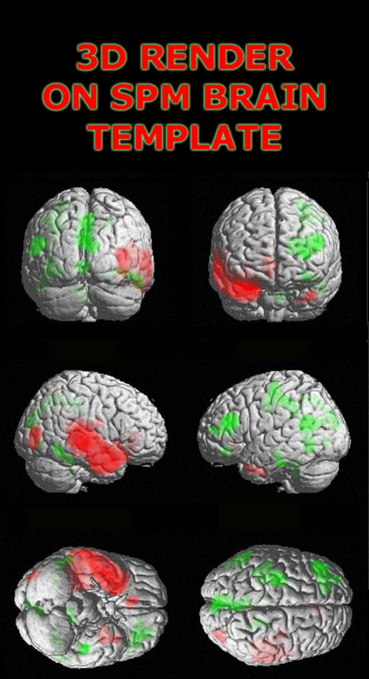
If you run your analysis in Radiologic convention, SPM will create your 3D flipped around so L=R (which we donít want since a 3D brain has an actual R and L, so this would get very confusing).
We descirbe two methods here to correct this problem. One is using an image editor (ImageJ) or a basic graphics software (e.g. Paint) to simply apply a flip to your final SPM 3D display,
so that the orientation is corrected. The other is using other imaging software, such MRIcro to create a 3D rendering in the correct orientation.
3D rendering using SPM2
- Go the Render menu from the display window and select Display.
- Choose 2 sets to display (both hyperperfusion and hypoperfusion).
- Select your SPM.mat file.
- Load each of the contrasts separately, following the same steps
as in Detailed Instructions section.
- After both contrasts have been loaded, you must select a template 3D brain.
SPM provides a high resolution template, render_single_sub.mat and a lower resoultion template with midsagittal views, render_spm96.mat.
These are available in ..\spm2\rend\.
- Specify More for brightness of blobs, and you'll have perfusion contrasts overlayed on a template brain. However, the problem with this is the orientation of the contrasts are flipped (left is right, right is left).
- A simple way to fix this problem is to do a quick horizontal flip for the anterior/posterior and left/right (lateral and mid-sagittal) views and a vertical flip for the dorsal/ventral views. You can use ImageJ to flip your images, or a graphics program such as Paint.
NOTE: Save only the final R/L corrected 3D images to avoid confusion.
Also, be sure to always double check your final 3D images against MRI sections
(see above) to confirm that the results make sense.
3D rendering using MRIcro
Another method is to use MRIcro to create a 3D rending of your results. The advantages of using MRIcro are there are no R/L orientation hassles. The disadvantages are that overlayed contrasts are not as detailed as the SPM2 results. For detailed instructions see Volume Rendering the Cortex.
A brief summary on how to create 3D renderings is described here.
- Open MRIcro File->Open template->ch2bet
- Click the 3D button.
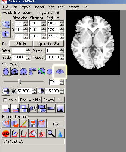
- You should see a 3D brain in 3 different planes. In the Render window that should have appeared, click the Overlay ROI/Depth box.
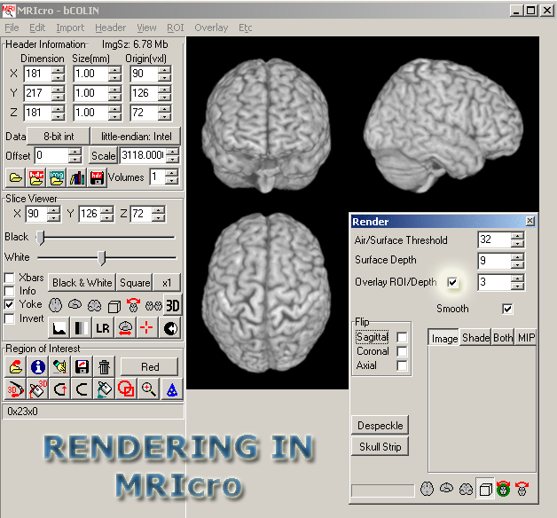
- Make sure that Overlay --> Load options --> Smooth overlay is NOT set
- Go to Overlay->Load 2 overlays [positive and negative]
- Select your HYPERPERFUSION image (that you created to make the 2D slice overlay image) for the POSITIVE header.
- Then, select your HYPOPERFUSION image for the NEGATIVE header.
- Then in the window that pops up change the positive range minimum to 0.01
(to match value used in disply_slices in SPM). The default for the maximum value is
automatically set at the maximum for the data. You can either leave this default in both
SPM and in MRIcro, or set them both to a fixed value. Recently we have used 8
for this value. Set the negative range the same way. Minimum cluster size should be left at 1. Then click Apply.
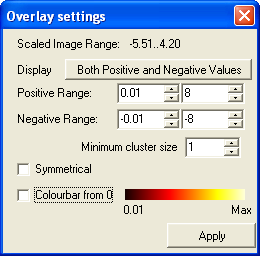
- Change the minimum cluster size to 1 and click Apply.
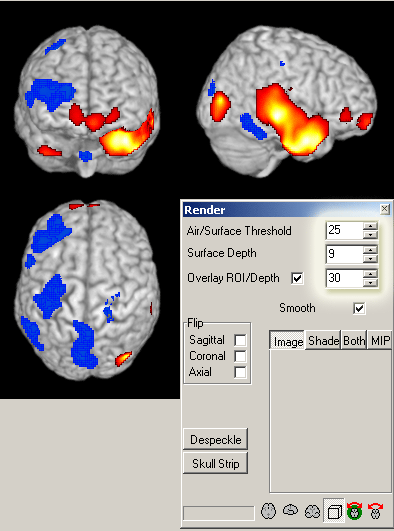
- Change the Overlay ROI/Depth to 30. The surface depth should be
9, and the Air/Surface threshold should be 25.
WARNING! The image below shows an incorrect representation
of the brain due to a bug in MRIcro.
While the superior and lateral views maintain the same L/R orientation, the anterior view
is incorrect (the R/L orientation has been flipped). The image below was created using MRIcro Version: 1.39 Build 2.
This error may be corrected in later versions of MRIcro.
- It is best to view your results using the Free-Rotate button. All views of the brain in this
option maintain the same L/R orientation.

- If your results are not displayed in the correct L/R orientation,
click the LR button in the main MRIcro window.
Remember for 3D projections, the L should be on the L of the brain.
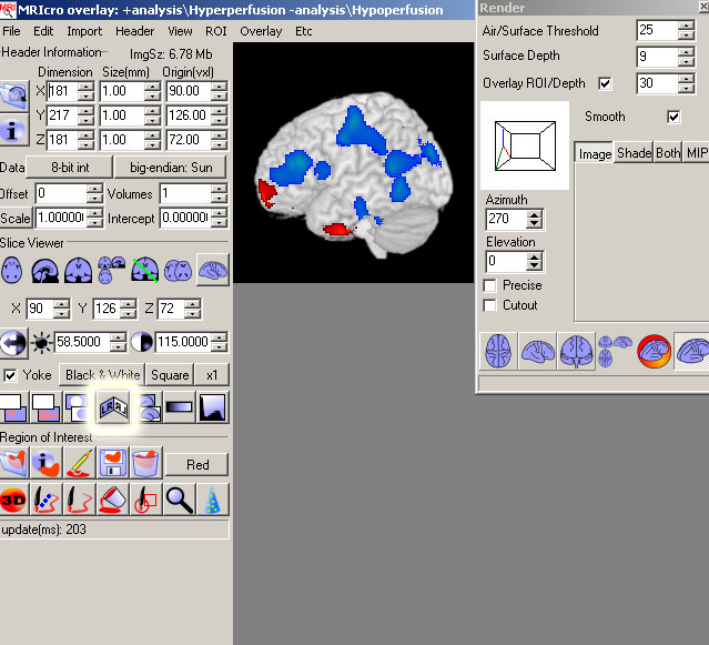
- Then in the Azimuth and Elevation boxes type the following for all of your views.
(Once you have 1 view, go to Edit->Copy, and paste the view in a MSPaint window and copy all of your views in the same file).
WARNING: Use these numbers for the different views, rather than the other buttons.
If you use the buttons to show the different views it can be flipped the wrong way.
- Right Lateral: Azimuth=270, Elevation=0
- Left Lateral: Azimuth=90, Elevation=0
- Anterior: Azimuth=180, Elevation=0
- Posterior: Azimuth=0, Elevation=0
- Superior: Azimuth=0, Elevation=90
- Inferior: Azimuth=180, Elevation= -90
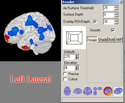
For the mid-sagittal views, click the cutout box, then the regions to cut out should be:
- To cut out the R side (view the middle, right):
- X: 89 1
- Y: 217 1
- Z: 181 1
- To cut out the L side (view middle, left):
- X: 181 90
- Y: 1 217
- Z: 181 1
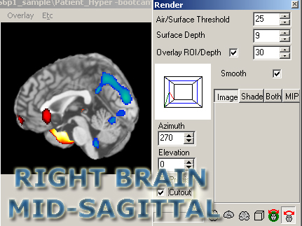
NOTE: Be sure to always double check your final 3D images against the
display on MRI sections (from above) to confirm that results make sense.
Back to Analysis Details
||
Jump to Top
||
Forward to Using Rview
|
|

|

